My internship: the experience and achievements

In this last post of the summer, which also marks the end of my summer internship, I would like to write a bit about my experience working for FlingOS™. Also, I would like to give you a summary of what has been achieved in the last nine weeks.

The experience

The internship has been a great experience. I have learnt a great deal about the x86 and MIPS32 processor architectures. Learning about these two very different designs alongside each other was truly valuable in recognising the merits of each approach and in learning about low-level development in general. Working on the IL to assembly conversion was fairly challenging but nevertheless fun. I also had a chance at writing and debugging substantial amounts of assembly code, which definitely worth the effort. Using Visual Studio and C# has given me a valuable experience in using the .NET framework as well. The internship provided me with skills I wouldn’t have learnt on my undergraduate course because most of the topics we covered during the summer are either not included or not discussed in such detail. So overall the experience with FlingOS™ has been a great addition to my studies. Although I was slightly intimidated by the amount of new information at the start, I think I managed to do well, with thanks to Ed for his patience and good teaching skills.

Achievements

During my internship, I helped to produce the resources for the upcoming tutorials, we achieved compiler support for MIPS and an extensive verification kernel has been created. The new kernel turned out to be very useful as we uncovered some errors from earlier implementations that caused problems in the compiler. The testing kernel, on which we have been working the last three weeks, has been a supreme success. It was great to see that the implementations worked as intended and also to detect a few corner-case bugs. To sum up, we not only have achieved what we have set out to do at the beginning but were also able to produce the verification kernel, which will definitely help future developments and improve the stability of FlingOS™.

Future plans

This week, my summer internship has come to an end, however, this does not mean farewell. Our plan is that I will continue to work for the project, during the coming academic year, as much as possible. I will also try and post here frequently to keep you up-to-date on what is happening here at FlingOS™, so you will definitely be seeing me around in the future.

Thank you for your interest in the project and thank you FlingOS™ for the great experience, it has been a great summer.

See you soon…

Roland

Cross-platform compiler verification kernel

The compiler verification framework I mentioned in last week’s post is currently under development and is due for completion by the end of next week. Of course, compiler testing never really reaches a completed state; new features can be added or old ones may require verification for a new use-case. So what I mean by completed is that by next week we will have included all the test cases we originally intended to include, which were decided upon after some thought and reasonably made assumptions. In the future, it is very likely that new test cases will be added to the framework. Our intended test cases will cover every expected (and many unexpected) use cases of the IL ops.

FlingOops™

The testing framework verifies the correctness of the compiler using behavioural testing, which essentially tests whether the IL to ASM conversions were correct. It is a behavioural testing framework because it tests the functionality of the compiler by testing the behaviour of the output and thus whether the compiler compiled correctly. It is also cross-architecture/cross-platform because it can be used for testing both the x86 and the MIPS architecture libraries (and any others we may add in the future).

The test kernel is called FlingOops™ and consists of a wrapper framework (with variations for different target architectures) and a long list of method calls, where each method contains a particular test relating to an operation as well as a message to the console stating whether the test case passed. Particular attention is paid to testing signed operations and the ones that require the handling of 64-bit values. To verify that signed and 64-bit values are calculated correctly, depending on the operation tested, we need to make sure that the carry- and borrow-bits are handled correctly as well as overflow happens as expected. There aren’t special carry and borrow flags on MIPS, so these have to be implemented by the compiler and therefore it is crucial to test the correctness of these implementations. The testing is going well and it is great to see that so far, all the test cases passed with the exception of a couple of small errors which were in the x86 target library. Thankfully these issues were fixed quickly as we were able draw from the knowledge and experience gained form working with MIPS viagra 100 mg 4 comprim. On the plus side, the detection of bugs in the x86 build demonstrated that our testing works!

For the last week

For the last week of my internship, our plan is to finalise the testing framework. I will post another article next week to confirm the completion of testing and to review my experience working for FlingOS™.

Thanks for reading! See you next week,
Roland

MIPS compiler support completed

For the last three weeks, we have been working towards completing the MIPS target architecture library. Finally this week, all the IL to ASM conversions have been added to the compiler. The implementations have been tested and we can confirm that we have compiler support for the MIPS32 processor architecture. So how did the testing go?

Testing

Some operations are fairly simple to test along the way, such as Add, Sub, Mul, Div, Shl etc., i.e. operations that use value types, since all we need to check is the result produced by a particular IL operation. The correctness of these operations can easily be verified without the need for a complete library. This is not the case for more complex operations, such as the ones related to objects, arrays and strings, i.e. reference types.

In order to check whether reference types function correctly, many different IL operations have to be implemented (NewObj, InitObj, Ldobj, Isinst etc), so we did not start testing these until the whole library was completed. The functionality of objects can be tested by creating a test class with some methods and fields within it. If these types initialise as expected then we can try to create a new instance of the class. If all these have been a success then we can test whether values passed to the class from outside return to the calling environment correctly. The testing of arrays and strings is a little more straight forward. In order to test arrays and strings, we can try to declare a new instance of these types and apply some basic array or string related manipulation to them and inspect the results.

During the testing process, some issues were uncovered. These issues were mainly related to the differences between the x86 and the MIPS architectures. On MIPS, only values contained in registers can be pushed onto the stack, while x86 lets the programmer push labels and immediate values directly, this is not available on MIPS. This is due to the CISC vs RISC architecture differences between x86 and MIPS. On MIPS, if we want to push a label onto the stack, we must first load the address of that label into a register, using the La instruction and then push that value from the register onto the stack. The same is true for immediate values; first we must move the value into a register then finally push that register onto the stack.

In many cases it is required to push the value zero onto the stack, but to do this we do not need to move zero to a general purpose register because MIPS has a $zero register which is fixed to the value zero. On MIPS there isn’t a Push or Pop assembly instruction as on x86, we need to simulate these operations with store/load instructions followed by adding to the stack pointer register using the Addi instruction.

There is another important thing to keep in mind when programming on MIPS. Data stored in memory must be aligned in such a way that an object’s address must start at a value that is some multiple of their own size in bytes, e.g. a 4-byte word must be 4-byte aligned but a single byte needs no alignment (a.k.a. single byte alignment). So if we want to load from/store to memory using an offset, we need to either make sure the data is aligned or access the data in multiple parts to avoid the alignment issues.

We never need to worry about this when accessing the stack through $sp or $fp since the compiler guarantees these are always 4-byte aligned. For other memory accesses, the FlingOS Compiler does not require memory to be aligned (for compatibility with other architectures). Instead, it uses runtime checks to load memory from or store memory to unaligned addresses. This means C# code can be written more generically, with less for the programmer to worry about but does create a small performance hit at runtime.

What’s next?

What we would like to do during the remainder of this summer is to add a unit testing framework to the project that formalises test cases for current and possible future architectures. This way we can ensure that the current supports for x86 and MIPS are stable and also, if the project is to be extended with a new target architecture library, then implementing that library can be done in an efficient way which is easily testable.

Thank you for reading this and if you are interested in the upcoming Launch Event then please subscribe on the FlingOS homepage.

See you soon…

Roland

Adding 64-bit values using 32-bit registers

Last week, I published a post discussing how to left shift 64-bit values using the available 32-bit sized registers on MIPS. This week, we thought I should do something similar which is to provide you with another article that describes a technique that solves another interesting problem. This time I will discuss how to add two 64-bit values. This may not seem difficult at first, however we must remember that MIPS processors do not have carry flags. We need the carry flag (or something equivalent) to preserve the result of an intermediate computational step. What we have to do is somehow simulate ‘Add with carry’ without the carry to allow for the addition of 64-bit integers using 32-bit registers.

Adding two 32-bit values is trivial since the operands and the result can be contained in single registers, so here we can just use a simple ‘add’ instruction, therefore carry is not needed. The sizes of the operands for the addition instruction are either 32 or 64 bits but in order to perform the addition, the sizes must match. An exception should be raised if the sizes are not the same. Before I discuss the method for adding two 64-bit values, let’s remind ourselves how signed and unsigned values are represented in 32-bit binary. The sign extension does not have an effect on the result of the computation due to the way two’s complement works, I only include it for completeness.

1

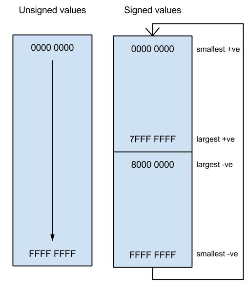
In the case of the unsigned values, the number of possible integer values goes from 0 to 232 and they are all positive, however if we want to represent signed integers in 32 bits then we need to use one bit, the most significant bit, to represent the sign, so we can represent both positive and negative integers in the range from 0 to 231. A negative value is derived such that you take a positive integer then you apply the method of two’s complement to it. Let’s see an example how to convert a positive number to its negative equivalent in 8-bit binary representation.

Two’s complement:

0000 1010   # = 10
1111 0101   # invert bits
0000 0001   # add 1
1111 0110   # = -10

First you take the integer as a bit string then you invert all the bits and finally you add one to the result. Two’s complement can also be used to convert a negative integer to positive.

Adding 64-bit operands

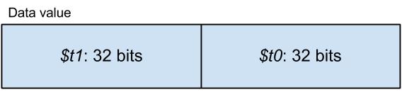
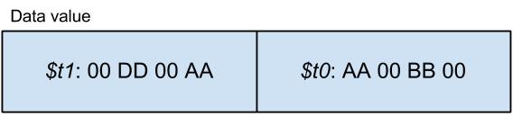
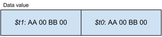
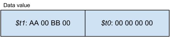
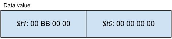
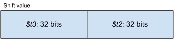
The two 64-bit integer operands have to be stored in two registers each. The first operand is stored as $t1:$t0, while the second operand is loaded as $t3:$t2.

1.      Add low bytes

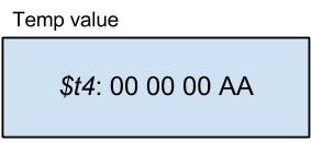
The first step of this algorithm is to add the two low bytes into $t4 which we will use as a temporary storage for this partial sum.

addu $t4, $t0, $t2

We use the unsigned operation because the low-bytes do not have a sign-bit as the upper bit! We also need a way to know if there is a carry from this partial calculation. For example if we add the following two binary numbers we get a result that cannot be represented in a single register (here I assume that the registers are 4 bits in size), i.e. there is a carry bit.

1111 + 0001 = 10000

What we can do here is to store the carry bit (the 5th bit if you like) in a temporary register in the next step.

2.      Simulate the carry flag

At this point we are going to use the ‘sltu’ instruction to store the carry bit in $t5.

sltu $t5, $t4, $t0

(Alternatively: sltu $t5, $t4, $t2 : either will do)

Here the ‘sltu’ instruction compares $t4 (sum of low bytes) with either of the individual set of low bytes ($t0 or $t2). The computation generated by the ‘sltu’ instruction goes like this. If $t4 < $t0 or if $t4 < $t2 then $t5 = 1, else $t5 = 0. It does not actually matter which set of low bytes we are using for the comparison because $t4 will always be smaller than any of the individual low bytes if there is a carry. But let me show you with some examples:

  1. $t0  =  0000
    $t2  =  0000
    $t4  =  0000       $t4 = $t0 = $t2         -> $t5 = 0

Here the computation does not generate a carry. We can see that $t5 has been set to 0 as required since $t4 is not less than either $t0 or $t2.

  1. $t0  =  0000
    $t2  =  1111
    $t4  =  1111       $t4 > $t0, $t4 = $t2    -> $t5 = 0

There isn’t any carry in this example either because $t4 is not less than either $t0 or $t2.

  1. $t0  =  0011
    $t2  =  0110
    $t4  =  1001       $t4 > $t0, $t4 > $t2    -> $t5 = 0

No carry because $t4 is not less than $t0 or $t2.

  1. $t0  =     0001
    $t2  =     1111
    $t4  =(1)0000       $t4 < $t0, $t4 < $t2    -> $t5 = 1

Now, in this example we do generate a carry, so let’s see if the method works. Remembering that $t4 is (for these examples) 4-bits in size, so the 5-th bit (the ‘1’) is lost: $t4 = 0000 because the carry bit is lost so, so $t4 < $t0 and $t4 < $t2 therefore $t5 is set to 1.

  1. $t0  =  1111
    $t2  =  1111
    $t4  =(1)1110       $t4 < $t0, $t4 < $t2    -> $t5 = 1

The last example works for the same reason as the previous one did.

Using my diagram above to visualise how numbers work, it is possible to see that no two numbers added together can ever wrap round over themselves, so the result will only ever be greater than either of the operands if there was no carry. The number system forms a cycle.

3.      Add high bytes with carry

Now, we need to add the two high bytes ($t1 and $t3) plus any carry that is left from the addition of the low bytes and store the result in $t1.

addu $t5, $t5, $t1      # $t5 = carry + $t1(high bytes of operand 1)
addu $t1, $t5, $t3      # $t1 = $t5 + $t3(high bytes of operand 2)

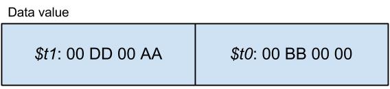
Finally we move the sum of the low bytes into $t0.
move $t0, $t4           # move partial sum to $t0

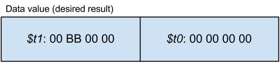
At the end of the process we have a result as a 64-bit value stored as $t1:$t0.

I hope you found this article helpful. See you soon…

Roland


Left shifting 64-bit values using 32-bit registers

Yesterday, while working on the implementation of the left shift IL operation (shl) for MIPS, we came across some challenges related to shifting 64-bit values using 32-bit registers. The solution is a bit tricky, so we thought it would be useful if I produced an article discussing how it can be done.

In order to shift a string of bits, we need two operands; the data itself and a value specifying the distance we want the data to be shifted. The shift value can either be a constant or a value stored in a register. Although in this article we assume that the values are in registers, the same technique can be adapted to be used with the assembly instructions that use constant values. There are four different cases we need to consider in terms of operand sizes:

  • 4-byte data, 4-byte shift value,
  • 4-byte data, 8-byte shift value (this is unsupported by C#),
  • 8-byte data, 4-byte shift value,
  • 8-byte data, 8-byte shift value.

The 4-8 case is unsupported by C#, so in this scenario the compiler throws an exception. The 4-4 case uses a single left shift assembly instruction (sllv) so there isn’t much explanation needed there.

8 – 4 case

In the 8-4 case, the 8-byte sized data is shifted by a value that is represented by a 4-byte binary number. Since we only have 32-bit (4-byte) registers, we need to store the data in two separate registers. One register contains the low bytes ($t0) while the other contains the high bytes ($t1). In this example, I store the shift value in $t2.

1

2

Consider a 1-byte left shift, i.e. $t2 contains the value of 8. Now we have a problem because the top byte of $t0 must replace the bottom byte of $t1 as well as the rest of the data must be shifted correctly. So how do we shift an 8-byte value using 4-byte registers? I will show you how by going through some examples. There are two variations of the 8-4 case; one where $t2 < 32 and another where $t2 >= 32.

The method ($t2 < 32)

Let’s say we want to left shift this data by 1 byte (1 byte can be represented by two hexadecimal digits):

3

Somehow we want the result to end up looking like this:

4

1.      Left shift high bytes by $t2

First, we want to left shift the high 4 bytes ($t1) of the original data by the value carried by $t2, which is 1-byte. The low 4 bytes remain unchanged for now. So we have:

5

2.      Right shift low bytes by (32 – $t2) into temporary

The next step is to logical right shift (not arithmetic right shift!) $t0 by (32 – $t2) into a register which we will use as a temporary storage, say $t4. Since $t2’s value in bits is 8, we right shift $t0 by 24 into $t4. This way we get the proportion of $t0 which we then want to copy into $t1. $t0 and $t1 remain unchanged at this point.

6


3.      OR temporary with high bytes

Here we can combine $t1 and $t4 using the logical OR operation to get the correct result for the high 4 bytes which we store back to $t1.

7


4.      Left shift low bytes by $t2

There is only one thing to do, left shifting the low 4 bytes ($t0) by $t2.


8

Now the algorithm is complete. If we compare this result with the desired result above, we can see that they are identical.

The method ($t2 >= 32)

If $t2 >= 32 then we are left shifting the data by 32 or more bits which means that the least significant bit (little endian) of the data is pushed beyond the low bytes into the high bytes. In all cases where the shift value is greater than or equal to 32, $t0 ends up filled with zeros and the content of $t1 are lost completely. But in what form does $t0 take over $t1? Let me show you step-by-step as before. Now let’s assume that we are left shifting by 40 bits and we have the same original data as before.


3

But this time we want the result to be this:

9


1.      Move low bytes into high bytes

We copy the contents of the low bytes into the high bytes. We do this to save the contents of $t0 into $t1. The original data becomes:

10


2.      Fill low bytes with zeros

Since the data is pushed all the way beyond the low bytes, we can fill the $t0 with zeros.

11


3.      Left shift high bytes by ($t2 – 32)

The final step is to left shift $t1 by ($t2 – 32) which is 8 in our case. So the desired result is achieved as expected.

12

 8 – 8 case

In the 8-8 case, both the data and the shift values are 8 bytes in size. There is one important observation we must make; shifting a 64-bit value by 64 bits or more is pointless since the result will always be zero. We also know that the number 64 is represented by this binary number: 0b0100 0000 which can easily be contained in the low bytes of the shift value ($t2). Actually any non-zero value beyond the 6th bit would yield a zero result but let’s just consider 4 bytes to be the smallest size we can manage.

 1 

13

To conclude, if $t3 is non-zero then the result of the left shift will definitely be zero, while if $t3 is zero then we can proceed the same way as in the 8-4 case by simply ignoring $t3.

I hope you found this article helpful. Please leave a comment if you think I missed something or if you have anything to add and I will do my best to respond.

See you around.

Roland


World first: C# kernel running on MIPS

Exciting news today as we announce our working kernel for MIPS based on the Creator CI20 board.

To the best of our knowledge, this is the first time in the world that anyone has got a C# kernel or operating system (of any form) working on a MIPS processor.

How did we do it?

We started the week by setting up the environment in which we were able to send a kernel binary file to the CI20. To see how this setup process is done, please read Ed’s post published earlier this week. After the connections were established we started to implement the necessary IL operations for the MIPS architecture to get the test kernel working.

The conversion of IL implementations from x86 to MIPS has been relatively smooth, except for the fact that in the MIPS architecture data stored in the memory must be half- or full-word aligned. This caused some initial headaches, however, Ed was determined to get to the bottom of the issue and in little time the problem was solved.

Other differences that required a lot of study and thought were related to the assembly code syntax for MIPS (GNU assembler – GAS) and the instructions available (reduced instruction set for MIPS). Although MIPS is a RISC architecture, meaning that more instructions must be used to perform the equivalent computation compared to x86, there are 16 general purpose registers available (as opposed to 4 on the x86) which makes implementation much easier. Furthermore, the programmer can also make use of pseudo-instructions which speed up implementation.

What does it do?

So what does the test kernel actually do? The answer is both not that much and quite a lot.

Although the functionality of the kernel is limited to changing the colour of the on-board LED and reading/writing characters from/to the UART ports, the fact that the kernel does that much proves that the FlingOS compiler is in a stable and solid state. It is a great proof of concept and initial step from which the new MIPS kernel can progress.

This has been a very exciting week and we are looking forward to completing the target architecture library and expanding the test kernel. In a few weeks time we will have a fully functioning IL compiler for MIPS.

Can I try it?

We’ll be releasing a compiler package and stable copy of the test kernel in the next month. We’d like to expand our compiler and proof-of-concept, test kernel a bit before releasing it to the wild.

Keep an eye on this space! Please ask questions below.

Ed and Roland