Earlier this week I tweeted that “Stage1: Boot a different OS – complete” meaning that I had successfully booted an alternative OS on the Creator CI20s (which were kindly provided by our sponsor Imagination Technologies®. Well, today I succeeded in booting a very basic custom operating system on the CI20s, so here’s how I did it.
For starters, I downloaded and installed the current compiler toolchain for Windows – Sourcey Codebench for MIPS available here. I installed mine to a non-standard directory but it works just fine. We’ll come on to how to use it later.
I also downloaded and install Putty and Serva – both of which are necessary tools. Putty provides a console interface to the serial connection required to talk to the CI20’s U-Boot bootloader. Serva provides an easy way to set up a TFTP server on Windows. Both of these tools are free. Again, we’ll come on to how to use them later.
Lastly, I had to buy one small (cheap) bit of extra hardware – a USB to UART converter. Be aware that there are two chips widely used to produce these devices. One of them only supports Linux and version of Windows 7 and earlier. The other chip supports Linux and all current versions of Windows – so make sure you get the right one! I bought one for Windows 8.1 (i.e. the second type of chip) from Amazon (with one day delivery on a Sunday no less!). I ordered from 3C4u who use Amazon. (The first time I tried to order two of these the package never arrived. I re-ordered and they were delivered fine. Amazon gave me a refund and Prime subscription extension for the first order so I’m not complaining too much!)
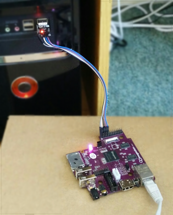
For the custom OS I wanted to try out something which I knew worked. So I went online and found Lardcave.net’s great series of tutorials on writing a custom CI20 OS. I cloned the Git repo and started following the instructions. For the USB to TTL chip I have, the tutorial is correct, you need to connect RXD on the converter to TXD on the CI20, and visa-versa for TXD on the converter and RXD on the CI20. To avoid having to use the power cable, you can also attach the 5V pin to abny of the CI20’s 5V_IN pins on the primary expansion header. The board will power on as soon as you connect the 5V pin so hold off until later for that! You’ll also need to connect an Ethernet cable to the same hub or switch your PC/laptop/WiFi hub is connected to – this will be so the CI20 can connect to the TFTP server.
After cloning the Git repo I ran across a few issues. The Lardcave.net tutorials were written for Max/Linux and for if you compile GCC yourself. Since I installed Sourcery CodeBench , the Makefile was not set up to compile properly. I eventually worked out how to it so it works properly. Here is a copy of my make file:
AS=mips-linux-gnu-as -mips32
CC=mips-linux-gnu-gcc
LD=mips-linux-gnu-ld
OBJCOPY=mips-linux-gnu-objcopy
CFLAGS=-Os

OBJS=start.o main.o

hello.bin: hello.elf
 $(OBJCOPY) -O binary $< $@

hello.elf: $(OBJS)
 $(LD) -EL -T linker.lds -o $@ $+

%.o: %.[Sc]
 $(CC) $(CFLAGS) -EL -c -o $@ $<

clean:
 rm -f *.o *.elf *.bin
I combined this with a simple batch script called build.bat in the same directory as the Makefile which allows me to specify the path to Sourcery CodeBench’s bin folder, instead of other version of GCC which I have installed. The batch script looked like this:
@echo off
SET BD=C:\Users\Ed\Documents\Coding\C\2015\MIPS\Compiler\bin
%BD%\cs-make
pause
@echo on
Where BD is set to the path to Sourcery CodeBench’s “bin” folder.
Having compiled the “hello.bin” file I proceeded to set up Putty and the TFTP server. Here are a series of images I took showing the process. By the time I was done entering the commands into Putty (also shown below), the CI20 showed the nice, purple LED as expected.
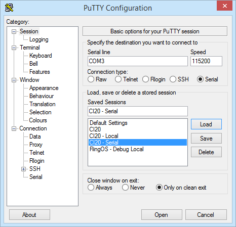
For the Putty configuration shown above, remember to update the COM port name to the name of the COM port device on your computer. This can be found by opening Device Manager and looking under the Ports node of the tree.
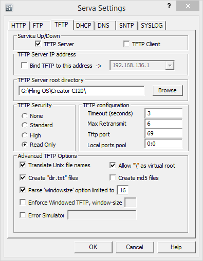
For the Serva configuration shown above, remember to update the “TFTP Server root directory” to the same folder as your “hello.bin” file is in.
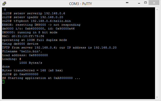
For the commands to U-Boot, remember to replace the serverip “192.168.0.6” and the ipaddr “192.168.0.20” with values for your network. The IP should be the IP address of the computer which is running Serva (which can be looked up by doing “ipconfig /all” in a Windows command prompt on the server computer). The “ipaddr” can be any value you like but the first three parts must match the IP address of your server.
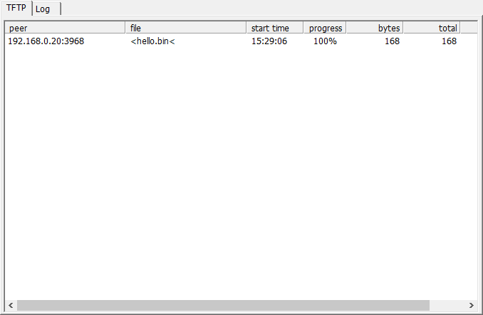
If the boot completes successfully, you should see a Serva log similar to the one above. The LED on the CI20 should turn purple as shown below.
Great start!
2 questions . . .
What’s the purpose of the AS macro in the makefile?
In the Putty session, why is the ‘go’ address different from the ‘load’ address?
The AS macro points to the assembler compiler (mips-linux-gnu-as with MIPS32 option). It isn’t used in that version of the makefile but is useful to have for anyone who wants to compile assembly files (.s files – extension is entirely necessary) directly rather than through GCC with the C files. Using AS will skip some of the C preprocessor stages which GCC runs over both C and Assembly code files.
The load address spat out by UBoot is actually incorrect. The load address is specified by the linker via the link script and is defined to be 0xA8000000. UBoot is capable of booting either the file you send it or the OS on the internal NAND. The default start address for the NAND image is 0x88000000. If you modify the linker script it is possible to set the load address to 0x88000000 which then blocks you from starting the NAND image. Also, 0xA8000000 is the uncached segment of kernel memory meaning the processor cache isn’t used. 0x88000000 is in the cached segment so the code runs a lot faster. Through UBoot (as demonstrated) it makes no difference but through a custom bootloader it makes a big difference as the cached area has to be separately initialised. This article provides some details about the various areas of the MIPS address space: http://www.johnloomis.org/microchip/pic32/memory/memory.html
🙂